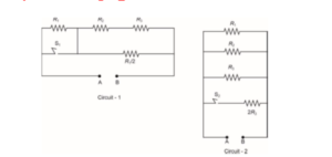
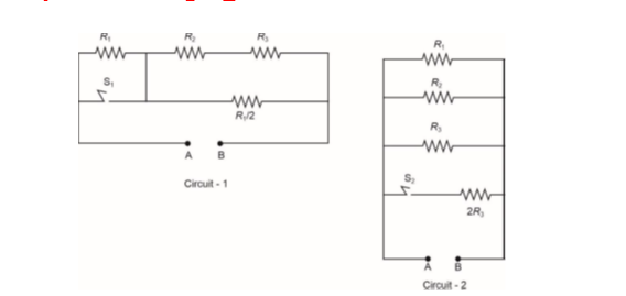
In Circuit-1 and Circuit-2 shown in the figures, $\mathrm{R}_1=1 \Omega, \mathrm{R}_2=2 \Omega$ and $\mathrm{R}_3=3 \Omega$.
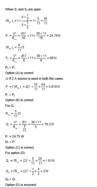
$P_1$ and $P_2$ are the power dissipations in Circuit-1 and Circuit-2 when the switches $S_1$ and $S_2$ are in open conditions, respectively. $Q_1$ and $Q_2$ are the power dissipations in Circuit-1 and Circuit-2 when the switches $S_1$ and $S_2$ are in closed conditions, respectively.